Visual Paradigm Installation and User's Guide: Difference between revisions
More actions
No edit summary Tag: Manual revert |
|||
| (65 intermediate revisions by the same user not shown) | |||
| Line 4: | Line 4: | ||
*Contact Shuokai Ma ([mailto:s214919@student.dtu.dk s214919@student.dtu.dk]) if you find a problem or have suggestions for this Wiki. | *Contact Shuokai Ma ([mailto:s214919@student.dtu.dk s214919@student.dtu.dk]) if you find a problem or have suggestions for this Wiki. | ||
= Visual Paradigm Installation = | = Visual Paradigm Installation = | ||
== | == Downloading, Installing and Activating Visual Paradigm == | ||
#Download the latest version of [https://www.visual-paradigm.com/download/ Visual Paradigm], and then install the Visual Paradigm by following the instructions of the installation wizard. | #Download the latest version of [https://www.visual-paradigm.com/download/ Visual Paradigm], and then install the Visual Paradigm by following the instructions of the installation wizard. | ||
#Start <span class="notranslate">Visual Paradigm. When you see the following screen, select '''Subscription/Academic License'''.[[File:Choose subscription 26064.png|500px|center|thumb|Select Subscription / Academic License]]</span> | #Start <span class="notranslate">Visual Paradigm. When you see the following screen, select '''Subscription/Academic License'''.[[File:Choose subscription 26064.png|500px|center|thumb|Select Subscription / Academic License]]</span> | ||
#Expand '''Academic Training Partner Program License'''. | #Expand '''Academic Training Partner Program License'''. | ||
#Copy the activation code from '''DTU Learn ( | #Copy the activation code from '''DTU Learn (Content -'''>''' UML Modelling Tools -'''>''' Visual Paradigm Academic License)'''. | ||
#Paste the activation code to the textbox called Activation Code. And then enter your name and student email address (sxxxxxx@student.dtu.dk).[[File:Activation code 26065.png|500px|center|thumb|Activating Visual Paradigm]] | #Paste the activation code to the textbox called '''Activation Code'''. And then enter your name and student email address (sxxxxxx@student.dtu.dk).[[File:Activation code 26065.png|500px|center|thumb|Activating Visual Paradigm]] | ||
#Click '''Activate'''. You are prompted for an activation code. | #Click '''Activate'''. You are prompted for an activation code. | ||
#Go to your email inbox and | #Go to your email inbox and check your new email for the verification code. | ||
#Copy the verification code and paste it to <span class="notranslate">Visual Paradigm</span>.[[File:Enter verification code 26066.png|500px|center|thumb|Pasting the verification code]] | #Copy the verification code and paste it to <span class="notranslate">Visual Paradigm</span>.[[File:Enter verification code 26066.png|500px|center|thumb|Pasting the verification code]] | ||
#Click '''OK '''to confirm. <span class="notranslate">Visual Paradigm </span>will be activated if the verification code is valid. | #Click '''OK '''to confirm. <span class="notranslate">Visual Paradigm </span>will be activated if the verification code is valid. | ||
= Visual Paradigm User's Guide = | = Visual Paradigm User's Guide = | ||
<p class="mwt-heading">In order to create a diagram, you need first to create a project.</p> | <p class="mwt-heading">In order to create a diagram, you need first to create a project.</p> | ||
== | == Creating your first project in Visual Paradigm == | ||
To create a project, select '''Project -> New''' from the toolbar.[[File:Create a new project 33403.png|500px|center|thumb|Create a new project]] | To create a project, select '''Project -> New''' from the toolbar.[[File:Create a new project 33403.png|500px|center|thumb|Create a new project]] | ||
| Line 56: | Line 57: | ||
| style="width: 70.0818%; height: 23px;" | Click to cancel creating the project, and close the window. | | style="width: 70.0818%; height: 23px;" | Click to cancel creating the project, and close the window. | ||
|} | |} | ||
Enter the name of the project and your name. And then you should choose '''UML''' as the Data type set and click '''Create Blank Project'''. | Enter the name of the project and your name. And then you should choose '''UML''' as the Data type set and click '''Create Blank Project'''. After creating a project, please '''[[#Saving the current project|save the current project]]''' first, since the autosave function will be enabled, if you do that. | ||
== UML modelling == | == UML modelling == | ||
This tutorial contains only the UML diagrams required for the course - Use Case Diagram, Class Diagram & Sequence Diagram. | |||
=== Use Case Diagram === | === Use Case Diagram === | ||
<p>Perform the steps below to create a UML use case diagram in <span class="notranslate">Visual Paradigm</span>.</p> | <p>Perform the steps below to create a UML use case diagram in <span class="notranslate">Visual Paradigm</span>.</p> | ||
#Select '''Diagram -> New '''from the application toolbar. | #Select '''Diagram -> New '''from the application toolbar. | ||
| Line 70: | Line 72: | ||
[[File:Create a new use case diagram.png|500x500px|center|thumb|Create a new use case diagram]] | [[File:Create a new use case diagram.png|500x500px|center|thumb|Create a new use case diagram]] | ||
==== | ==== Creating a system ==== | ||
To create a system in the use case diagram, select '''System''' on the diagram toolbar and then click it on the diagram pane. Finally, name the newly created system when it is created.[[File:Create a system 25217.png|200px|center|thumb|Create a system]] | To create a system in the use case diagram, select '''System''' on the diagram toolbar and then click it on the diagram pane. Finally, name the newly created system when it is created.[[File:Create a system 25217.png|200px|center|thumb|Create a system]] | ||
==== | |||
==== Creating an <span class="notranslate">actor</span> ==== | |||
<span class="notranslate">To draw an actor in a use case diagram, select '''Actor''' on the diagram toolbar and then click it on the diagram pane. Finally, name the newly created actor when it is created.</span> | <span class="notranslate">To draw an actor in a use case diagram, select '''Actor''' on the diagram toolbar and then click it on the diagram pane. Finally, name the newly created actor when it is created.</span> | ||
<span class="notranslate"></span>[[File:Creatre an actor 25218.png|300px|center|thumb|Create an actor]] | <span class="notranslate"></span>[[File:Creatre an actor 25218.png|300px|center|thumb|Create an actor]] | ||
==== | |||
==== Creating a use case ==== | |||
You can then create a use case through Resource Catalog by doing the following: | You can then create a use case through Resource Catalog by doing the following: | ||
#Move the mouse over a source shape (e.g. an actor). | #Move the mouse over a source shape (e.g. an actor). | ||
#Press on the '''Resource Catalog''' button and drag it out.[[File:Resource catalog 26845.png|300px|center|middle|thumb|Resource Catalog]] | #Press on the '''Resource Catalog''' button and drag it out.[[File:Resource catalog 26845.png|300px|center|middle|thumb|Resource Catalog]] | ||
#Release the mouse button until it reaches your preferred place. ( | #Release the mouse button until it reaches your preferred place. (E.g. in the system box)[[File:Release the mouse button in the system box.png|200px|center|middle|thumb|Release the mouse button in the system box.]] | ||
#Select '''Association -> Use Case''' from Resource Catalog.[[File:Create use case from resource catalog 26846.png|300px|center|middle|thumb|To create a use case]] | #Select '''Association -> Use Case''' from Resource Catalog.[[File:Create use case from resource catalog 26846.png|300px|center|middle|thumb|To create a use case]] | ||
#The source shape and the newly created use case are connected. Finally, name the newly created use case.[[File:Use case created 26847.png|300px|center|middle|thumb|Use Case created]] | #The source shape and the newly created use case are connected. Finally, name the newly created use case.[[File:Use case created 26847.png|300px|center|middle|thumb|Use Case created]] | ||
=== Class Diagram === | === Class Diagram === | ||
<p>Perform the steps below to create a UML class diagram in <span class="notranslate">Visual Paradigm</span>.</p> | <p>Perform the steps below to create a UML class diagram in <span class="notranslate">Visual Paradigm</span>.</p> | ||
#Select '''Diagram -> New '''from the application toolbar. | #Select '''Diagram -> New '''from the application toolbar. | ||
| Line 92: | Line 95: | ||
#'''Enter''' the diagram name and maybe also the description. The '''Location''' field enables you to select a model to store the diagram. We are '''not''' going to change this value right now. | #'''Enter''' the diagram name and maybe also the description. The '''Location''' field enables you to select a model to store the diagram. We are '''not''' going to change this value right now. | ||
#Click '''OK'''. | #Click '''OK'''. | ||
[[File:Create a new class diagram.png| | [[File:Create a new class diagram.png|500px|center|thumb|Create a class diagram]] | ||
==== Creating a class ==== | ==== Creating a class ==== | ||
| Line 99: | Line 102: | ||
Then a class will be created.[[File:Class created 26923.png|300px|center|thumb|Class created]] | Then a class will be created.[[File:Class created 26923.png|300px|center|thumb|Class created]] | ||
==== Creating an attribute ==== | ==== Creating an attribute ==== | ||
To create an attribute, right-click the class and select '''Add -> Attribute''' from the pop-up menu.[[File:Create attribute 25124.png| | To create an attribute, right-click the class and select '''Add -> Attribute''' from the pop-up menu.[[File:Create attribute 25124.png|400px|center|thumb|Create attribute]] | ||
Then an attribute is created.[[File:Attribute created 2538.png|300px|center|thumb|Attribute created]] | Then an attribute is created.[[File:Attribute created 2538.png|300px|center|thumb|Attribute created]] | ||
You can modify the | You can modify the specification of the attribute by right-clicking the attribute and selecting '''Open Specification''' from the pop-up menu.[[File:Attribute specification.png|500px|center|thumb|Attribute Specification ]] | ||
==== Creating an operation ==== | ==== Creating an operation ==== | ||
To create an operation, right-click the class and select '''Add -> Operation '''from the pop-up menu.[[File:Create operation 25125.png| | To create an operation, right-click the class and select '''Add -> Operation '''from the pop-up menu.[[File:Create operation 25125.png|400px|center|thumb|Create operation]] | ||
Then an operation is created.[[File:Operation created 2541.png|300px|center|thumb|Operation created]] | Then an operation is created.[[File:Operation created 2541.png|300px|center|thumb|Operation created]] | ||
You can modify the | You can modify the specification of the attribute by right-clicking the operation and selecting '''Open Specification''' from the pop-up menu.[[File:Operation specification.png|500px|center|thumb|Operation Specification]] | ||
==== Creating an association ==== | ==== Creating an association ==== | ||
| Line 117: | Line 120: | ||
#Press on the '''Resource Catalog''' button and drag it out.[[File:Using resource catalog 26921.png|300px|center|thumb|Using Resource Catalog]] | #Press on the '''Resource Catalog''' button and drag it out.[[File:Using resource catalog 26921.png|300px|center|thumb|Using Resource Catalog]] | ||
#Release the mouse button at the place where you want the class to be created. If you want to connect to an existing class, drop at that class. Otherwise, drop at the empty space (either at the diagram background or container shape like package). | #Release the mouse button at the place where you want the class to be created. If you want to connect to an existing class, drop at that class. Otherwise, drop at the empty space (either at the diagram background or container shape like package). | ||
#If you are connecting to an existing class, select '''Association''' from '''Resource Catalog'''. If you are creating a new class, select '''Association -> Class''' from '''Resource Catalog'''. If you want to create an aggregation or composition, select '''Aggregation -> Class or Composition -> Class''' instead.[[File:Create associated class 26922.png| | #If you are connecting to an existing class, select '''Association''' from '''Resource Catalog'''. If you are creating a new class, select '''Association -> Class''' from '''Resource Catalog'''. If you want to create an aggregation or composition, select '''Aggregation -> Class or Composition -> Class''' instead.[[File:Create associated class 26922.png|400px|center|thumb|Create a class]] | ||
#If you are creating a new class, you should see the class now and it is connected to the source shape. Enter its name and press '''Enter''' to confirm editing.[[File:Associated class created 26917.png|300px|center|thumb|Associated class created]] | #If you are creating a new class, you should see the class now and it is connected to the source shape. Enter its name and press '''Enter''' to confirm editing.[[File:Associated class created 26917.png|300px|center|thumb|Associated class created]] | ||
===== | ===== Editing the navigability of the association ===== | ||
To edit the navigability of an association end, right-click near the association end, select '''Navigable''' from the popup menu and then select the '''true''' value.[[image:edit_navigability_25126.png|500px|center|thumb|Edit navigability]] | To edit the navigability of an association end, right-click near the association end, select '''Navigable''' from the popup menu and then select the '''true''' value.[[image:edit_navigability_25126.png|500px|center|thumb|Edit navigability]] | ||
===== | ===== Editing the multiplicity of the association ===== | ||
To edit the multiplicity of an association end, right-click near the association end, select '''Multiplicity''' from the popup menu and then select a multiplicity.[[File:Edit multiplicity 25126.png|500px|center|thumb|Edit multiplicity]] | To edit the multiplicity of an association end, right-click near the association end, select '''Multiplicity''' from the popup menu and then select a multiplicity.[[File:Edit multiplicity 25126.png|500px|center|thumb|Edit multiplicity]] | ||
===== | |||
===== Editing the direction of the association ===== | |||
To show the direction of an association, right-click on it and select '''Presentation Options -> Show Direction''' from the pop-up menu.[[File:Show direction 25123.png|500px|center|thumb|Show direction]] | To show the direction of an association, right-click on it and select '''Presentation Options -> Show Direction''' from the pop-up menu.[[File:Show direction 25123.png|500px|center|thumb|Show direction]] | ||
==== Creating a generalization ==== | ==== Creating a generalization ==== | ||
You can create a subclass by doing the following: | You can create a subclass by doing the following: | ||
| Line 132: | Line 137: | ||
#Press on the '''Resource Catalog''' button and drag it out.[[File:Using resource catalog 26918.png|300px|center|thumb|Using Resource Catalog]] | #Press on the '''Resource Catalog''' button and drag it out.[[File:Using resource catalog 26918.png|300px|center|thumb|Using Resource Catalog]] | ||
#Release the mouse button at the place where you want the subclass to be created. If you want to connect to an existing class, drop at that class. Otherwise, drop at the empty space (either at the diagram background or container shape like package). | #Release the mouse button at the place where you want the subclass to be created. If you want to connect to an existing class, drop at that class. Otherwise, drop at the empty space (either at the diagram background or container shape like package). | ||
#If you are connecting to an existing class, select '''Generalization''' from Resource Catalog. If you are creating a new class, select '''Generalization -> Class''' from Resource Catalog.[[File:Select generalization 26919.png|300px|center|thumb| | #If you are connecting to an existing class, select '''Generalization''' from Resource Catalog. If you are creating a new class, select '''Generalization -> Class''' from Resource Catalog.[[File:Select generalization 26919.png|300px|center|thumb|Create a subclass]] | ||
If you are creating a new class, you should see the class now and it is connected to the source shape with a generalization. Enter its name and press '''Enter''' to confirm editing.[[File:Subclass created 26920.png|300px|center|thumb|Subclass created]] | If you are creating a new class, you should see the class now and it is connected to the source shape with a generalization. Enter its name and press '''Enter''' to confirm editing.[[File:Subclass created 26920.png|300px|center|thumb|Subclass created]] | ||
==== Creating a dependency from/to attribute/operation ==== | ==== Creating a dependency from/to attribute/operation ==== | ||
You can also add a dependency from and/or to an attribute or operation in class by doing the following: | You can also add a dependency from and/or to an attribute or operation in class by doing the following: | ||
#Select '''Dependency''' from the diagram toolbar.[[File:Select dependency 27435.png|300px|center|thumb|Dependency]] | #Select '''Dependency''' from the diagram toolbar.[[File:Select dependency 27435.png|300px|center|thumb|Dependency]] | ||
#Press on the source shape or a class member.[[File:To press on source element 27432.png|300px|center|thumb| | #Press on the source shape or a class member.[[File:To press on source element 27432.png|300px|center|thumb|Press on the source operation]] | ||
#Drag to the target shape, or a class member.[[File:Dragging to class member 27433.png|300px|center|thumb|Dragging to the target attribute]] | #Drag to the target shape, or a class member.[[File:Dragging to class member 27433.png|300px|center|thumb|Dragging to the target attribute]] | ||
#Release the mouse button to create the dependency.[[File:Dependency created 27434.png|300px|center|thumb|Dependency created between an operation and a member]] | #Release the mouse button to create the dependency.[[File:Dependency created 27434.png|300px|center|thumb|Dependency created between an operation and a member]] | ||
=== Sequence Diagram === | === Sequence Diagram === | ||
<p>Perform the steps below to create a UML sequence diagram in <span class="notranslate">Visual Paradigm</span>.</p> | <p>Perform the steps below to create a UML sequence diagram in <span class="notranslate">Visual Paradigm</span>.</p> | ||
#Select '''Diagram -> New '''from the application toolbar. | #Select '''Diagram -> New '''from the application toolbar. | ||
| Line 159: | Line 164: | ||
#Press on the '''Resource Catalog''' button and drag it out.[[File:Create lifeline 26851.png|300px|center|thumb|Using Resource Catalog]] | #Press on the '''Resource Catalog''' button and drag it out.[[File:Create lifeline 26851.png|300px|center|thumb|Using Resource Catalog]] | ||
#Release the mouse button at the place where you want the lifeline to be created. | #Release the mouse button at the place where you want the lifeline to be created. | ||
#Select '''Message -> LifeLine''' from Resource Catalog.[[File:Select message 26852.png|500px|center|thumb| | #Select '''Message -> LifeLine''' from Resource Catalog.[[File:Select message 26852.png|500px|center|thumb|Create a lifeline]] | ||
#A new lifeline will be created and connected to the actor/lifeline with a message. Enter its name and press '''Enter''' to confirm editing.[[File:Lifeline created 26853.png|400px|center|thumb|Lifeline created]] | #A new lifeline will be created and connected to the actor/lifeline with a message. Enter its name and press '''Enter''' to confirm editing.[[File:Lifeline created 26853.png|400px|center|thumb|Lifeline created]] | ||
==== Auto extending activation ( | ==== Auto extending activation (Adding a new message / Adding a new activation) ==== | ||
When creating a new message between lifelines/actors, activation will be automatically extended.[[File:Extend activation 2117.png|300px|center|thumb|Auto extending activation]] | When creating a new message between lifelines/actors, activation will be automatically extended.[[File:Extend activation 2117.png|300px|center|thumb|Auto extending activation]] | ||
| Line 172: | Line 177: | ||
Then the overlapping execution is split.[[File:Overlapping execution split.png|500px|center|thumb|The overlapping execution is split]] | Then the overlapping execution is split.[[File:Overlapping execution split.png|500px|center|thumb|The overlapping execution is split]] | ||
==== Creating a combined fragment for messages ==== | ==== Creating a combined fragment for messages ==== | ||
To create a combined fragment to cover messages, | To create a combined fragment to cover messages, select the messages, right-click on the selection and select '''Create Combined Fragment''' and then select a combined fragment type (e.g. loop) from the popup menu.[[image:create_combined_fragment_14702.png|500px|center|thumb|Create a combined fragment for messages]] | ||
A combined fragment of the selected type will be created to cover the messages.[[ | A combined fragment of the selected type will be created to cover the messages.[[image:loop_2178.png|500px|center|thumb|The combined fragment created]] | ||
=== | == Exporting the diagram from the project == | ||
<p class="mwt-heading" ><span style="font-size: 12pt;" ><span style="color: rgb(224, 62, 45);" >'''[ATTENTION]'''</span> I recommend exporting the diagrams in PDF format, as PDF diagrams are vectors and therefore scalable.</span></p> | |||
=== Exporting the diagram as a PDF file (<span style="color: rgb(224, 62, 45);">Recommended</span>) === | |||
You can export the opening diagram to an image file by doing the following: | |||
#Select '''Project -> Export -> Active Diagram as Image...''' from the toolbar. | |||
#Select the image format as '''PDF files (*.pdf vector graphic)''' at the bottom of the window.[[File:Save as pdf.png|500px|center|thumb|Export the diagram as a PDF file]] | |||
#Specify the filename. | |||
#Click <strong style="font-size: 14.4px;">Save </strong><span style="font-size: 14.4px;">to export.</span> | |||
== | === Exporting the diagram as an image === | ||
You can export the opening diagram to an image file by doing the following: | You can export the opening diagram to an image file by doing the following: | ||
#Select '''Project -> Export -> Active Diagram as Image...''' from the toolbar. | #Select '''Project -> Export -> Active Diagram as Image...''' from the toolbar. | ||
| Line 189: | Line 201: | ||
- Without background: ignore the background colour by exporting transparent background.</pre> | - Without background: ignore the background colour by exporting transparent background.</pre> | ||
== | == Switching the different diagrams in the current project == | ||
You can switch the different diagrams in the current project by | You can easily switch the different diagrams in the current project by pressing '''ctrl + tab'''. | ||
== | == Saving the current project == | ||
You can save your current project by doing the following: | You can save your current project by doing the following: | ||
#Select '''Project -> Save''' | #Select '''Project -> Save '''from the toolbar. | ||
#Specify the filename. | #Specify the filename. | ||
#Click | #Click '''Save '''to save the project. | ||
== Importing / Opening your project == | |||
You can import / Open your current project by doing the following: | |||
#Select '''Project -> Open '''from the toolbar. | |||
#Choose the project you want to import/open. | |||
#Click '''Open '''to import/open the project. | |||
[[Category:Course 02161 Software Engineering 1|2]] | |||
Latest revision as of 19:30, 5 January 2024
READ ME FIRST
- This tutorial only applies to the WINDOWS operating system, other operating systems have not yet been verified.
- This tutorial is based on this website with simplifications and modifications. You can visit that website for more detailed UML information and guidelines.
- Contact Shuokai Ma (s214919@student.dtu.dk) if you find a problem or have suggestions for this Wiki.
Visual Paradigm Installation
Downloading, Installing and Activating Visual Paradigm
- Download the latest version of Visual Paradigm, and then install the Visual Paradigm by following the instructions of the installation wizard.
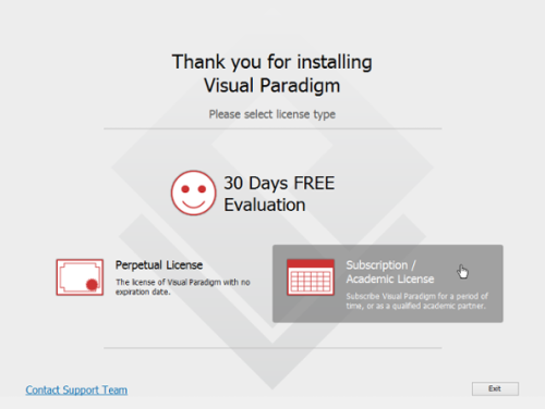
- Start Visual Paradigm. When you see the following screen, select Subscription/Academic License.
Select Subscription / Academic License - Expand Academic Training Partner Program License.
- Copy the activation code from DTU Learn (Content -> UML Modelling Tools -> Visual Paradigm Academic License).
- Paste the activation code to the textbox called Activation Code. And then enter your name and student email address (sxxxxxx@student.dtu.dk).
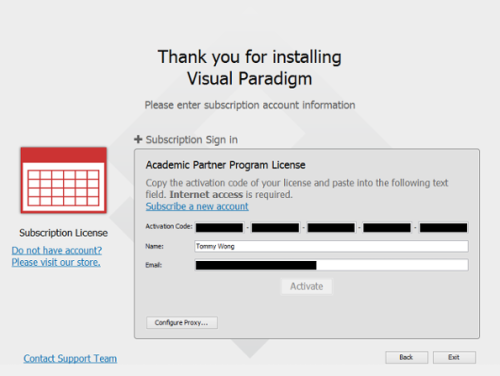
Activating Visual Paradigm - Click Activate. You are prompted for an activation code.
- Go to your email inbox and check your new email for the verification code.
- Copy the verification code and paste it to Visual Paradigm.
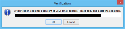
Pasting the verification code - Click OK to confirm. Visual Paradigm will be activated if the verification code is valid.


Visual Paradigm User's Guide
In order to create a diagram, you need first to create a project.
Creating your first project in Visual Paradigm
To create a project, select Project -> New from the toolbar.

The New Project window appears.

| No. | Name | Description |
| 1 | Name | The name of the project. |
| 2 | Author | The person who creates the project. |
| 3 | Data type set | It lets you select the programming/scripting language for the project. The language you selected mainly affects class modelling. For example, the selectable visibilities and primitive types vary among languages. |
| 4 | Description | The project description. |
| 5 | Create Project Management Lookup | Check it to automatically fill the project management lookups such as iteration, version, etc with default lookup values. |
| 6 | Create Blank Project | Click to create the project. |
| 7 | Cancel | Click to cancel creating the project, and close the window. |
Enter the name of the project and your name. And then you should choose UML as the Data type set and click Create Blank Project. After creating a project, please save the current project first, since the autosave function will be enabled, if you do that.
UML modelling
This tutorial contains only the UML diagrams required for the course - Use Case Diagram, Class Diagram & Sequence Diagram.
Use Case Diagram
Perform the steps below to create a UML use case diagram in Visual Paradigm.
- Select Diagram -> New from the application toolbar.
- In the New Diagram window, search and select Use Case Diagram, and then click Next.
- You can choose to create a blank diagram or use the template. We choose to create a blank diagram here.
- Enter the diagram name and maybe also the description. The Location field enables you to select a model to store the diagram. We are not going to change this value right now.
- Click OK.

Creating a system
To create a system in the use case diagram, select System on the diagram toolbar and then click it on the diagram pane. Finally, name the newly created system when it is created.

Creating an actor
To draw an actor in a use case diagram, select Actor on the diagram toolbar and then click it on the diagram pane. Finally, name the newly created actor when it is created.

Creating a use case
You can then create a use case through Resource Catalog by doing the following:
- Move the mouse over a source shape (e.g. an actor).
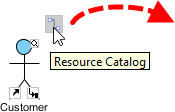
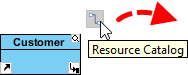
- Press on the Resource Catalog button and drag it out.
Resource Catalog - Release the mouse button until it reaches your preferred place. (E.g. in the system box)
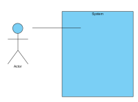
Release the mouse button in the system box. - Select Association -> Use Case from Resource Catalog.
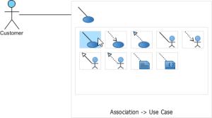
To create a use case - The source shape and the newly created use case are connected. Finally, name the newly created use case.
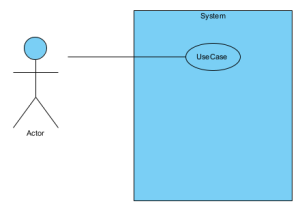
Use Case created


Class Diagram
Perform the steps below to create a UML class diagram in Visual Paradigm.
- Select Diagram -> New from the application toolbar.
- In the New Diagram window, search and select Class Diagram, and then click Next.
- You can choose to create a blank diagram or use the template. We choose to create a blank diagram here.
- Enter the diagram name and maybe also the description. The Location field enables you to select a model to store the diagram. We are not going to change this value right now.
- Click OK.

Creating a class
To create a class in a class diagram, click Class on the diagram toolbar and then click on the diagram.

Then a class will be created.

Creating an attribute
To create an attribute, right-click the class and select Add -> Attribute from the pop-up menu.

Then an attribute is created.

You can modify the specification of the attribute by right-clicking the attribute and selecting Open Specification from the pop-up menu.

Creating an operation
To create an operation, right-click the class and select Add -> Operation from the pop-up menu.

Then an operation is created.

You can modify the specification of the attribute by right-clicking the operation and selecting Open Specification from the pop-up menu.

Creating an association
You can create an associated class in a class diagram by doing the following:
- Move your mouse pointer over the source shape.
- Press on the Resource Catalog button and drag it out.
Using Resource Catalog - Release the mouse button at the place where you want the class to be created. If you want to connect to an existing class, drop at that class. Otherwise, drop at the empty space (either at the diagram background or container shape like package).
- If you are connecting to an existing class, select Association from Resource Catalog. If you are creating a new class, select Association -> Class from Resource Catalog. If you want to create an aggregation or composition, select Aggregation -> Class or Composition -> Class instead.
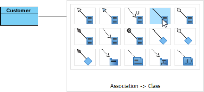
Create a class - If you are creating a new class, you should see the class now and it is connected to the source shape. Enter its name and press Enter to confirm editing.

Associated class created


To edit the navigability of an association end, right-click near the association end, select Navigable from the popup menu and then select the true value.

Editing the multiplicity of the association
To edit the multiplicity of an association end, right-click near the association end, select Multiplicity from the popup menu and then select a multiplicity.

Editing the direction of the association
To show the direction of an association, right-click on it and select Presentation Options -> Show Direction from the pop-up menu.

Creating a generalization
You can create a subclass by doing the following:
- Move your mouse pointer over the superclass.
- Press on the Resource Catalog button and drag it out.
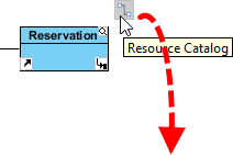
Using Resource Catalog - Release the mouse button at the place where you want the subclass to be created. If you want to connect to an existing class, drop at that class. Otherwise, drop at the empty space (either at the diagram background or container shape like package).
- If you are connecting to an existing class, select Generalization from Resource Catalog. If you are creating a new class, select Generalization -> Class from Resource Catalog.
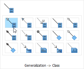
Create a subclass


If you are creating a new class, you should see the class now and it is connected to the source shape with a generalization. Enter its name and press Enter to confirm editing.

Creating a dependency from/to attribute/operation
You can also add a dependency from and/or to an attribute or operation in class by doing the following:
- Select Dependency from the diagram toolbar.
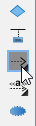
Dependency - Press on the source shape or a class member.
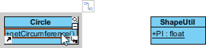
Press on the source operation - Drag to the target shape, or a class member.

Dragging to the target attribute - Release the mouse button to create the dependency.

Dependency created between an operation and a member


Sequence Diagram
Perform the steps below to create a UML sequence diagram in Visual Paradigm.
- Select Diagram -> New from the application toolbar.
- In the New Diagram window, search and select Sequence Diagram, and then click Next.
- You can choose to create a blank diagram or use the template. We choose to create a blank diagram here.
- Enter the diagram name and maybe also the description. The Location field enables you to select a model to store the diagram. We are not going to change this value right now.
- Click OK.

Creating an actor
To create an actor, click Actor on the diagram toolbar and then click on the diagram.

Creating a lifeline
To create a lifeline, you can use Resource Catalog:
- Move your mouse pointer over the source lifeline.
- Press on the Resource Catalog button and drag it out.
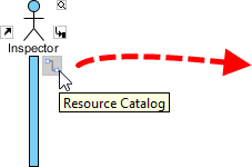
Using Resource Catalog - Release the mouse button at the place where you want the lifeline to be created.
- Select Message -> LifeLine from Resource Catalog.
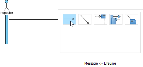
Create a lifeline - A new lifeline will be created and connected to the actor/lifeline with a message. Enter its name and press Enter to confirm editing.
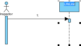
Lifeline created


Auto extending activation (Adding a new message / Adding a new activation)
When creating a new message between lifelines/actors, activation will be automatically extended.

If you want to split the newly created activation into two or more, you can check the section Spitting overlapping execution (activation) below.
Spitting overlapping execution (activation)
You can split the overlapping execution (activation) by right-clicking the execution and selecting Spit Overlapping Execution.

Then the overlapping execution is split.

Creating a combined fragment for messages
To create a combined fragment to cover messages, select the messages, right-click on the selection and select Create Combined Fragment and then select a combined fragment type (e.g. loop) from the popup menu.

A combined fragment of the selected type will be created to cover the messages.

Exporting the diagram from the project
[ATTENTION] I recommend exporting the diagrams in PDF format, as PDF diagrams are vectors and therefore scalable.
Exporting the diagram as a PDF file (Recommended)
You can export the opening diagram to an image file by doing the following:
- Select Project -> Export -> Active Diagram as Image... from the toolbar.
- Select the image format as PDF files (*.pdf vector graphic) at the bottom of the window.
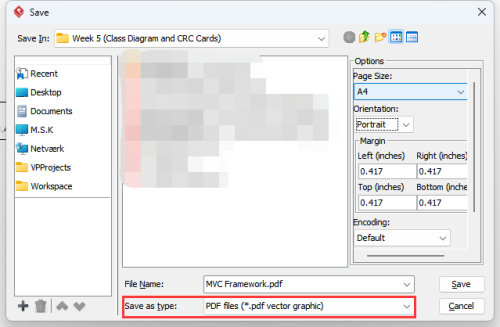
Export the diagram as a PDF file - Specify the filename.
- Click Save to export.

Exporting the diagram as an image
You can export the opening diagram to an image file by doing the following:
- Select Project -> Export -> Active Diagram as Image... from the toolbar.
- In the Save window, set the image quality. The higher the quality, the clearer the image, and the larger the image size.
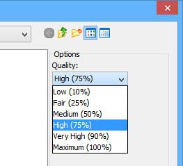
Set the image quality - Select the image format at the bottom of the window.
- Specify the filename.
- Click Save to export.

NOTE: There are two options for exporting as PNG files - with and without background:
- With background: export diagram's background colour.
- Without background: ignore the background colour by exporting transparent background.
Switching the different diagrams in the current project
You can easily switch the different diagrams in the current project by pressing ctrl + tab.
Saving the current project
You can save your current project by doing the following:
- Select Project -> Save from the toolbar.
- Specify the filename.
- Click Save to save the project.
Importing / Opening your project
You can import / Open your current project by doing the following:
- Select Project -> Open from the toolbar.
- Choose the project you want to import/open.
- Click Open to import/open the project.